Scene Designer is the primary design application designers will use to create 2D and 3D graphics available in Prime Playout Mode.
Prime Title Bar
Application Menus
- File
- Edit
- View
- Window
- Tools
- Config
- Help
Version Identifier
- The Chyron Prime version currently being ran
- Chyron Prime Engine version currently installed and being ran
- File Name the canvas is currently focused on
Release Notifications
When a New Release is available, the Notifications Icon will display a Green Circle.
Click on the Release Notifications Icon to display the latest available versions.
- Latest Bug Fix Version: latest bugfix build based on the version currently running
- Latest Prime Version: shows the latest Minor version available based on the Major Version you are running
- Newest Prime Version: Newest major version available
- Users may need to purchase New Licensing in order to download and run this version)
- Download Area: Links directly to the main Download Area
- *If no updates are available, only the Download Area link will be present
Clicking on any one of the release notifications will open up your Windows default internet browser and link you directly to that release in the Chyron Download Area.
| Note: The Chyron Download Area, also known as the Chyron DA, allows users to download the Chyron products they licensed, read through the latest release notes, download Qualified NVIDIA drivers, and download additional files. |
Prime projects
| See the Projects section of this guide for more about creating and opening projects. |
Designer tabs
Quickly and easily navigate between multiple files at once.
To re-organize tabs, drag and drop the tabs next to each other by utilizing the drop indicator line. Reorganizing the tabs on the Project Bar will automatically reorder your open files within the Window menu.
Designer tab shortcut keys
Quick access shortcut keys are available for Tabs. Please see the Designer Shortcut Keys section of this document to learn how to access and modify shortcut key bindings.
- Ctrl + Tab will tab / cycle through Tabs from left to right
- Ctrl + Shift + Tab will tab / cycle through Tabs from right to left
Hovering your mouse over a Designer Tab will display the file path
Live Mode
The Designer can be output to any of the defined outputs in the Playout Configuration. This allows for Realtime output previews. Select from the list of outputs. The currently selected output is “Program”.
Design for specific licensed options
You can enable/disable software features to match your playout license. This gives you the ability to target systems that are licensed differently.
The toolbar has some quick pick shortcuts based on PRIME's use case pricing model. Select the options you would like to enable. You can load/save these settings.
File Menu
New Scene: Create a new scene (.pbx). Useful to have a base scene and its elements when new scenes are created. New Base Scene: Create a new base scene (.pbs) to be referenced by normal (.pbx) scenes. New Master Control Panel: Create a new Master Control Panel (.mcp) New Transition: Create a new transition (.pbt) New Clip Transition Create a New Clip Transition (.pct) New Switcher Transition: Create a New Switcher Transition (.pst) Application Logic: Create and Edit Application Logic (.pal) See the separate “Application Logic” Section for more details. Edit Current Project: Edits the current project in the scene editor. This allows for custom resource objects to be loaded when the project is selected. Open: Open a File Open Recent: Open a Recently Opened File Save: Save the File Save As: Save the File as a different file name Save Image: Captures an image of the current state of the canvas Save as CAMIO File .CRD files are currently generated when ‘Saving to CAMIO’ from the Prime Designer. This process automatically exports the file into the Chyron CAMIO Context and Folder defined by the CAMIO export settings in Prime.
CAMIO Upload: Upload your scene directly to CAMIO. Please see the CAMIO Import FBX: Allows for importing FBX models. Refer to the Model object. (.fbx) Import Vector: Allows for importing .AI. PDF and .SVG files. Please refer to the Importing Vector Files and Polygon object sections of this guide. Import AE:Allows importing of After Effects Projects when using the AE\Prime Exporter. (.json) Prime 5.2 introduces new AE Export / Import functionalities. Please refer to the “PRIME After Effects Guide” for all details. Edit Messages: Shows the Edit Scene Messages window. This allows for visualizing and editing the messages built off of a Scene in a table view. Close: Closes the File you have selected/focused Close All: Close all opened files Exit: Exits the Prime Designer Application, but not Playout or Prime Engine |
Importing Vector Files
Designers can import vector files into PRIME by opening Prime Scene Designer and going to File > Import Vector. Unlike the direct Polygon object Vector Import method, this method allows designers to import all supported layers individually at once. Each supported vector layer will be imported into the Prime scene’s scene tree separately. Please see Vector File Compatibility details below.
Supported File Types
- .SVG
- .AI
Import Vector Dialog
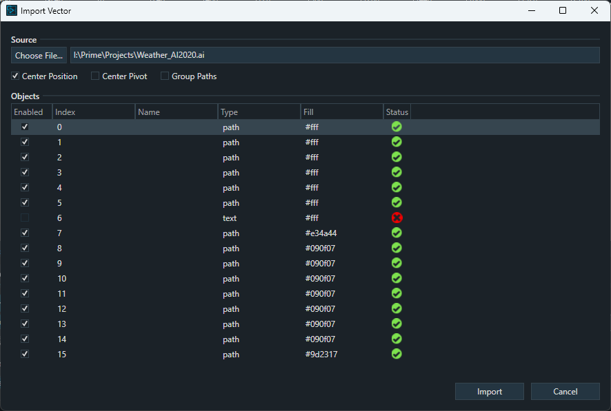
- Center Position
- Centers the polygons in the scene
- Center Pivot
- Centers the pivot point for each layer
- Group Paths
- The end result will be one polygon object in the scene created from all the data in the vector file.
- Uncheck this option if you want all supported layers to come into PRIME individually
- The end result will be one polygon object in the scene created from all the data in the vector file.
- Enabled
- Select which polygons in the file you would like to import by selecting the check box under Enabled. If an element is not supported, the Enabled checkbox is disabled by default and can't be enabled.
- Index
- Layer # from the file
- Name
- layer name if specified within the file
- Type
- type of element
- Fill
- Displays the Color Hex value it will import. Users can edit the color value during import if needed.
- Status
- Can display 3 different status types
- Green Check mark = Supported
- Yellow Exclamation = May not import correctly as the element contains an unsupported attribute or effect
- Red X = Unsupported Element
- Can display 3 different status types
File > Import Vector Method Scene Tree Example:
Vector File Compatibility
*Please Note - Vector Import results will vary as not all Illustrator Designs, tools, and functionality scenarios are compatible since this can vary greatly. If a supported object is not importing please try outlining, vectorizing, or expanding the object first before importing into PRIME.
- Color Import Support
- RGB color space Only.
- CMYK color space is not supported and will not convert properly
- Only Fill Colors are supported
- Stroke, Gradient and Mesh Colors are not supported
- SVG files offer the best RGB color accuracy
- .AI and .PDF RGB color values may differ slightly in Prime
- RGB color space Only.
- .AI and .PDF Illustrator Tool Prime Import Support
- For Best Results and Performance - We recommend using the same Artboard size as your PRIME Scene Resolution.
- Shapes, Draw, Modify, Open and Closed Paths, and Type Tools are supported but results can vary
- The Line Segment Tool is not supported. Lines will be imported into PRIME however due to the lack of a Stroke color option in PRIME, it will appear hidden.
- Clipping Maks and Compound Paths results will vary
- Illustrator Effect Support will vary
- Photoshop Effects are not supported
- 3D is not supported
- Type must be outlined (Non-Outlined / Editable Type will not import into Prime)
- Outlined Area Type, Type on Horiz and Vert Path, and Vertical Text is supported
- Images are not supported
- The Blend Tool support will vary. We do not recommend importing with Smooth Color Spacing or high steps / distance values as each blend step will import as its own individual path.
- .SVG Prime Import Support
- Exact vector shape and layer compatibility will vary
- .AI and .PDF file types offer superior vector object support than .SVG files
- RGB color value accuracy is greater with .svg files
Saving Vector Images from Adobe Illustrator for PRIME
- Open or Create artwork in Illustrator based on the supported Vector options notes above
- Go to File > Save
- Choose your preferred save location
- Save as Type
- Select either .AI, .PDF, or .SVG
- For .SVG - If needed, choose the required artboard you will to save out (artboards are not supported in PRIME
- For .PDF - All and Range are supported in PRIME, however only 1 page can be imported at a time during the PRIME Import Vector process.
- Select either .AI, .PDF, or .SVG
- (.ai) Save Options
- Files must be saved out as Illustrator 2020
- Create PDF Compatible File option must be turned on
- Illustrator artboards are not supported, single artboard only
- (.pdf) Save Options
- Please use the [Illustrator Default] pdf save options
- Multiple PDF Pages are supported in PRIME, however you can only import one page at a time within PRIME’s import vector process.
- (.svg) Save Options
- Please use the Default SVG 1.1 save options
Designer Settings
General
- New Scene: Optional to define a default scene whenever New scene (ctrl + N) is created.
- Layout: Auto Save Layout enabled will save all layout changes to the currently loaded layout. With this setting disabled, you must manually save any layout changes to the specified .wxel file.
- Default Region of Interest: Define numeric values for Top, Left, Bottom and Right for the default region of interest guideline that will be displayed for each new scene. (0,0,0,0 is fullscreen)
- Thumbnail: Default height of thumbnail image
Canvas Settings
- General: Allows for visual control of selected objects.
- Color: Allows setting background color, region of interest color, ruler guide color.
- Safe Title: Allows for visual control of the canvas safe title guides.
- Ruler Guides
- Creating Guides: By default, objects will snap to ruler guides. You can adjust snapping settings in the Tools menu.
- Lock guides: You can also lock all guides from the Tools menu. This can be handy when you have lots of objects in your scene and you don’t want to accidentally select a ruler guide.
Create a ruler guide
To begin creating a ruler guide:
- Open the designer.
- Open the tools menu and choose “Create Guide.”
- This will open the Guide Form, from which you can define the dimension and position of your new guide. The default shortcut to open this form is Ctrl+Alt+G.
Alternatively, you can create guides by dragging them onto the designer canvas.
- Ensure sure you are in the designer and that rulers are shown (Tools > Rulers/Ctrl+R).
- Click on a ruler and drag your mouse onto the canvas.
- A new guide will be created and placed wherever you drop it.
Hide all guides
To temporarily hide guides
- Go to Tools > Show Guides
- Toggle between show/hide to change the visibility.
Delete one guide
To delete a guide:
- Drag the guide onto a ruler
- The guide will automatically be deleted.
Delete all guides
To delete all guides:
- Go to Tools > Clear Guides.
Align guides (Smart Guides)
Determines if the built-in alignment tools (Smart Guides) should align text objects by its bounding box or the bounds of the text itself.
Copy/Paste mode
- Renumber Parent only: When you copy and paste a group, only the pasted parent will autoincrement the suffix number value of the group name.
- Renumber Parent and Children: When you copy and paste a group, the pasted parent as well as all children objects will auto-increment the suffix number value of their node name.
Control Panel Settings
Default Control Panel Size - Default size of new Control Panels
Control Placement - When new Controls are added to a Control Panel, this determines the direction in which they are placed.
Left to Right Example:
Top to Bottom Example:
Scene Tree Settings
Search
Display Results
- Filter: With filter selected, only objects that meet the search criteria in the scene tree search bar will be displayed in the scene tree.
- Highlight: With highlight selected, all objects in the scene tree will remain visible, and those that meet the search criteria of the scene tree search bar will be highlighted.
Action Settings
Timeline
- Move Cursor with Keyframe - moves the playhead and cursor to the keyframe
- Always Show Cursor - always shows or hides the vertical timeline playhead cursor line
Animations > Background
Parent
Hide
Show
Default State
- Expanded or collapsed
- Show Expanded when Keyframes Present
- Show Expanded when Selected
Keyframes
- Default Interpolation: Sets the default keyframe behavior.
- Show Gridlines: Show or hide canvas gridlines
- Auto Default Keyframes: Adds keyframes to the “Default” action when keyframes are created in other Actions. Example: add “PositionX” into the setting then create a new action and you will see “PositionX” in the timeline. Add as many properties as you need. Separate them by commas. “PositionX,PositionY,ScaleX”.
- Default Ease Length: When a new “ease” keyframe is added, set the default ease to some value.
Properties
- Show Properties: Define which properties you would like to be automatically added to the Timeline Editor when a new action is created.
Behavior
- Never: If a second object of the same type is added to the Action the properties listed will not show.
- Empty: Remove properties defined in the “Show Properties” that have no keyframes.
- Selected: Shows the properties with or without keyframes from the selected object.
- Always: Always show the properties when the object has no keyframes.
Save
- Video Format: Select the video format when saving actions to a clip file. Right clicking on the Action tab allows users to record the animation to file.
- Action is saved using first output channel and certain restrictions apply based resolution of the Output Channel
- 4K Support. Only DNxHR codes supports resolution higher than 1080p
- Interlace Support. DNxHD does not support.
- Save Action to Clip will only honor auto follow source mode on the first frame of the selected action. If autofollow expressions (including position and size) are evaluated after the initial keyframe then the render will not evaluate. For example if the source object's position or size changes during the animation, then autofollow will not evaluate on the target object.
- Default Location: Set the folder where Action clips will be stored
Copy/Paste
- Paste mode
- Create New Actions
- Paste in Existing Actions
Project Settings
Text Settings
- Default Style: Select from the list of Styles (Refer to the “Text” section on Styles). This style will be the default style each time a new text object is added to your scene.
- Enable Tab Key to Cycle Text Objects: With this option enabled the tab key will cycle to the next text object in the scene tree and automatically places focus in the properties text field. This allows you to quickly and easily update text fields within your scene in Prime Designer. Focus must be on either the Scene Tree, Canvas or Text Editor for this feature to function. Shift Tab cycles to previous text objects.
Configuration (Designer Canvas)
*Changing this configuration will not affect Playout Channels
*Checked on (Enabled) by Default to use the first playout configuration channel
Use First Playout Configuration Channel
Uses the very first PRIME Playout Configuration Channel Settings to configure the PRIME Scene Designer Canvas output settings (Traditional Method from all Previous PRIME Versions).
| Video Standard | Output resolution and frame rate to be used for the channel |
| Range | SDR or HDR (Windows HDR PQ Only) *Special Note If you are designing in HDR but do Not have an HDR Monitor, change this setting to SDR to prevent the Designer Canvas being washed out due to no HDR Monitor being used |
| Depth | 8Bit or 10Bit |
| Audio Mode | Chooses output audio type: Disabled or System Audio |
| Audio Device | Can be set to Primary Sound Driver to use the default audio output from the system, or to any of the audio devices available to the system |
| Audio Channels | The number of audio output channels |
| Antialiasing | Sets the antialiasing for the output: Disabled, Multi Sample 2x-16x, Coverage Sample (Quality) 8x-16x |
*After changing the settings, you will need to restart PRIME for the new settings to take effect
Scene Tree Node Coloring: Enable color coding in the scene tree will also color code the shaded areas above.
- To enable Node Coloring, right click on the toolbar left of the Scene Node where the “Lock” icon is located.
Canvas Properties
Axis Mode
Toggles between Local and World Axis View modes.
- World Axis View: When you move an object using this coordinate system, you are moving it relative to the space of the viewport.
- Local Axis View: Uses the coordinate system of the selected object.
Auto Select
Toggles between Auto Select and Lock Selection
- Auto Select: The active selection changes to where the user clicks on the Canvas.
- Lock Selection: The active selection is persistent regardless of where the user clicks on the Canvas. Changing focus is done on the Scene Tree.
Selecting overlapping objects
Right-clicking on the Canvas at the point where two or more objects overlap will display a context menu of the overlapping objects. Objects with the same not are not distinguished in this menu.
Alt+left click at the overlapping area will cycle through the overlapping objects.
Pan and Zoom
Use the “-“and “+” buttons on the slider control or your mouse wheel for zoom control.
Hold the middle mouse wheel down to pan the canvas. Zoom will “Zoom to Mouse”
Show Wireframe-Normals-Key
Show Bounding Box-Manipulators
Custom Canvas Resolutions
This property is part of the “Scene/Resolution” property.
Selecting “Custom” will bring up the following dialog:
Playout configuration
The Prime Scene Designer Canvas derives the starting resolution from the first output channel within Prime Playout Configuration. Any Custom resolutions set in the Playout Configuration will be enumerated in the Canvas Resolutions list automatically and vice versa.
Setting up HDR within Windows
To enable HDR for the Prime Scene Designer Canvas, your Windows Display Settings must be configured to use HDR. The monitor you will be using to display Prime Designer must be a HDR-capable monitor in order to turn on HDR in Windows.
- Enable HDR in Windows 10:
- Select the Windows Start Button, then select Settings > System > Display.
- Choose the HDR-capable display under Rearrange your displays.
- Select Windows HD Color settings
- Under Display capabilities, check to make sure it says Yes next to Use HDR.
- Turn on Use HDR.
Enable HDR in Windows 11:
- Select the Windows Start Button, then enter Settings. Select Settings > System > Display.
- Choose the HDR-capable display at the top of Display Settings.
- Scroll down to HDR under Brightness & Color and switch HDR to On.
Prime Scene Designer HDR canvas setup
Once HDR is set up within Windows, please startup Prime and navigate to Playout. Select Config > Playout Configuration. The Prime Scene Designer Canvas is tied to the first output channel within Playout Configuration unless it has been overridden by PRIME Designer’s Canvas Configuration in Prime Designer Settings. Due to this, please set either the first output channel to a Device type that will allow you to select HDR 10 Bit or manually setup the Prime Designer Canvas Configuration to HDR. Please see the Configuration (Designer Canvas) section of this document for details.
HLG and S-Log3 based HDR are not available for use with the Canvas. However, if your first Output Channel is set to HLG or S-Log3, the canvas will automatically use HDR 10 Bit. LUT files are not compatible with HDR or Prime’s Scene Designer Canvas. HLG based channels are the only type of channel which supports LUT files as outlined in the Prime Playout Configuration User Guide.
Even if your first output video channel is set to HLG with a selected LUT file, the LUT will Not be applied and displayed on the Canvas itself. It will only be applied to the Playout Video Output Channel itself as the Canvas does not support LUTs.
When HDR is enabled for the first Playout Video Channel but your monitor does not have HDR enabled within Windows, the Prime Scene Designer Canvas will appear washed out like in this example.
Please see the Prime Playout Configuration User Guide for channel setup instructions and further HDR, HLG, and S-Log3 details.
Scene properties
The following scene properties are displayed:
- Description: The user may enter a simple description of the scene
- Keywords: Add metadata to search for scenes
- Style: Can be linked to a CAMIO context and changed in LUCI. See Style Sheets for more.
- Message Id: Messages recorded from this scene will start recording at the specified location or the next available location. When a message is read, PRIME will read in the base message and fulfill the template with the data from the message.
- Channel (On): Recall the scene will play to the defined channel
- Layer (On): Recall the scene will be positioned in the defined layer on output
- Effect In: When the scene plays use these triggers in the trigger list as the Effect In. Usually it’s just an Action or Condition to effect in
- Effect Out: Execute these triggers when the scene transfers from Program to Preview
- Layer In: Triggers when a scene in Preview plays to Program replacing another scene in the same layer. This supersedes the “Effect In”.
- Layer Out: Triggers when a scene in Program is played off by an incoming scene in the same layer. This supersedes the “Effect Out”.
- Preview In: Executes when a scene is loaded into Preview. The Defined “Effect In” will still execute when the scene is played. This is useful for LUCI previews in a CAMIO workflow.
- Update Behavior: Only applies when the scene is playing on Output and the same scene (or message based on same) is cued to played next
- Update Values: On playback of the cued scene, the cued scene updates the replaceable values of the playing scene without replacing the playing scene from the output
- Replace Scene: On playback of cued, the playing scene is fully replaced by the cued scene. Layer In and Layer Out will be used if defined. Otherwise, Effect In and Effect Out will be used.
- Auto Priority: An incoming scene takes priority over an outgoing scene. To adjust the priority, uncheck Auto Priority and change the value in the Scene Properties > Render section of the Scene Group. The default is 2000. Auto Priority will override the Z position of multiple scenes in the same channel.
- Resolution: Set the resolution format for the scene.
- Region of Interest: Set the Region of interest for the scene that can be used in designer to crop; save image and save clip files. (0,0,0,0 for Left, Top, Right and Bottom bounds is fullscreen resolution with no cropping applied).
- Size: Reward only text for final size of defined region of interest
- Set to Graphics Bounds: Selecting this button will update region of interest values to calculate the utmost bounding edges for top, left, bottom and right of all objects combined in the scene.
- Thumbnail: Set the thumbnail that will be used in PRIME’s scene browser.
- Use Region of Interest: Enable this to crop the thumbnail to the defined region of interest in the scene
- *This will only be applied to Prime’s scene browser and does not apply to LUCI thumbnails and previews.
Command Sequence
The command sequence allows you to build a list of Trigger items to play out in a sequence:
Adding a Command allows you to choose an item from the Trigger list:
The right Green arrow indicates whether the item, after being executed, will move to the next item in the list. This is called “Follow Through”. Some items, like Action, can ONLY be follow through.
The Command Sequence has its own API and can be controlled by a Condition, A script or from a Control Panel.
C# Script: Scene.CommandSequence.Execute
Condition
Control Panel
Scene Events
Before Load: Executes once before a scene is loaded into either Preview or Program Effect In: Triggers when a scene is transferred to Program. (See Layer In) Effect Out: Triggers when a scene is transferred from Program to Preview or Scene is closed. (See Layer Out) Layer In: Triggers when a scene in Preview plays to Program replacing another scene in the same layer. This supersedes the “Effect In”. Layer Out: Triggers when a scene in Program is played off by an incoming scene in the same layer. This supersedes the “Effect Out”. Preview In: Triggers when a scene is loaded into Preview. Supersedes the Effect In for Preview. Before Load: Triggers before a scene is loaded into Program After Load: Triggers once after a scene is loaded into either Preview or Program Before Play: Triggers before a scene is played from Preview to Program After Play: Triggers after a scene is played to output Before Update: Triggers before the elements of a scene are loaded. After Update: Triggers after the elements of a scene are loaded. Before Stop: Triggers when a scene is taken off Program After Stop: Triggers after a scene is taken off Program Before Close: Triggers before a scene is closed. (Cleared from both Preview and Program) After Close: Triggers after a scene is closed. (Cleared from both Preview and Program) Style Changed: Triggers when the scene’s Style Property is changed (See Style Property) |
Opening a scene directly to output will trigger Before load, After Load, Before Play and After Play.
All of the scene events handlers can be used to attach any of the other objects methods in the scene. EX:Timer1.Start
Image description: Example of assigning an “Effect In” and “Effect Out”